How to Install a Old Work Electrical Box
 Old Work Electrical Boxes
How to install an electrical box into an existing wall or ceiling
- POST a QUESTION or COMMENT about how to install and wire electrical outlets or receptacles in buildings.
InspectAPedia tolerates no conflicts of interest. We have no relationship with advertisers, products, or services discussed at this website.
Installing an "old-work" electrical box or receptacle refers to methods used to add a metal or plastic electrical box into an existing wall or ceiling without having to make extensive cuts into the building surfaces.
Here we describe types of old work electrical boxes and devices used to secure those boxes in place safely.
This article series describes how to choose, locate, and wire an electrical receptacle in a home. Electrical receptacles (also called electrical outlets or "plugs" or "sockets") are simple devices that are easy to install, but there are details to get right if you want to be safe.
We also provide an ARTICLE INDEX for this topic, or you can try the page top or bottom SEARCH BOX as a quick way to find information you need.
Choosing & Installing an Old Work Electrical Box
 Examples of Old Work Electrical Boxes & Methods of Installation
When an electrical circuit and electrical boxes are being added to an existing structure wires are snaked through building cavities to the desired fixture location and an old-work electrical box or "junction box" is installed to contain electrical splices and devices.
Both metal and plastic old-work electrical boxes are available and there is a variety of clips, clamps, and other devices used to secure electrical boxes in a wall or ceiling when the box cannot be conveniently nailed or screwed directly to the structure.
[Click to enlarge any image]
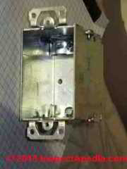
At above is a steel gang box with mounting hardware to permit old-work installation: those metal brackets at the top and bottom of the box can be screwed to a wall surface.
In my opinion I'd prefer to see this box used in a wood or paneled wall or on a plaster wall on wood lath rather than on simple drywall as I worry that in a receptacle installation someone may find they pull the whole installation off of the drywall when removing a wall plug.
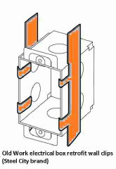
Below we illustrate thin steel clips (colored orange) that have been used (with considerable care) to secure a steel gang box in a drywall or plaster wall (adapted from Steel City products).

Adding these clips can make the box far more secure in the wall than if we only use the brackets shown in the left and center illustrations.
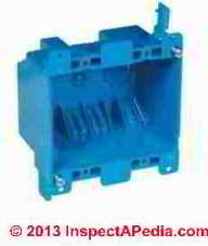
Here are two rectangular old-work switch or receptacle boxes.
Above left is a Carlon 25 cubic inch 2-gang plastic electrical box.
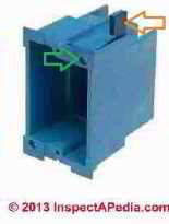
Just above is an old-work plastic Zip Box suitable for a single electrical switch or receptacle. The blue ear shown at the electrical Zip Box top at right (orange arrow) is pulled against the interior surface of the wall plaster or drywall as the installation screw (green arrow) is turned.
Below, using a Carlon round 81 cubic-inch oldwork box as an example, we show the mounting screws that cause the swing-clamps to open and then pinch the box against plaster or drywall through which the box has been mounted (red arrows).
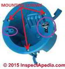
The purple circle and smaller oval show us where the device-mounting screws (receptacle, switch, light-weight lamp fixture bracket) will be secured.
You can see that the three swing-clamps for this old work box are in the open position but they'd be moved to a closed position to insert the box through a round opening cut in drywall or plaster.
Watch out: As we discuss at PLASTIC ELECTRICAL BOX REPAIR, the round blue Carlon electrical box at above right includes a metal grounding lug shown in our larger purple circle.
This Carlon # B618RP-UPC is a 4 1/4" diameter electrical box that has a UL 514C listing, meets NEMA OS-2, and is specifically indicated by the manufacturer as not for fixture support in the ceiling.
That article illustrates a failure where this box was used to hang a ceiling light fixture. The light began to fall out of the ceiling.
Below is another old-work plastic electrical box being installed in a ceiling.
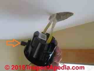
Shown above, the rotating swing-clamps on the plastic old work box are open for illustration (yellow arrow).
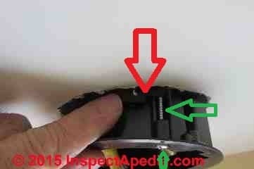
The swing clamps are pressed flat against the box sides (red arrow at above right) as it is pushed through its mounting hole into the ceiling or wall cavity.
As the box mounting screws (green arrow) are turned the plastic ears rotate open and then are pulled tight against the drywall or plaster ceiling or wall surfaces, pulling the old work electrical box flange against the exposed side of the ceiling or wall and holding it in place.
In new construction an old-work box may be also needed if the electrician is asked to leave a wire exposed for future installation of fixture whose precise location has not been determined. In this case she may leave the wire protruding through a ceiling or wall and may plan on later re-locating the wire precisely using an old work retrofit type electrical box.
See PLASTIC ELECTRICAL BOX REPAIR for an example of selecting and installing an old work electrical box to power a ceiling-mounted light fixture
Watch out: do not rely on old work boxes with minimal support (just drywall, for example) to carry heavier fixtures or ones subject to vibration or movement such as a ceiling fan. Such installations are unsafe.
Question: when were "Madison Bars" first used to install old work electrical boxes?
 Ken The Old House Guy said:
Hi. My electrician found Madison Bars in my house. Do you know when they began being used in homes? - 2020/04/24
This Q&A were posted originally at ALUMINUM WIRING REPAIR FIELD NOTES
[Click to enlarge any image]
Moderator reply: 1967 or later
Hi OHG, and thanks for a helpful question.
The earliest simplified flat steel electrical box mounting clip or "F" clip patents I've found (so far - there may be earlier versions) in the U.S. are from the 1950s, such as Shepard's "Wall Outlet Box Mounting" cited at the link I'll give below.
IF your electrical box supports are actually a Madison Electric Company product, then, while the history of the Madison Electric Company extends back to 1914, the first official use of that name was in 1957, so it's not likely that your "Madison Bars" are older than that.
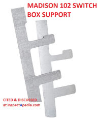
Most-likely, if your old work electrical box is mounted using the very simple, thin metal folded box supports shown below then that product is probably from 1960s, as Madison patented an electrical box support in 1967 (cited below).
See Albrecht, David B. ELECTRICAL BOX SUPPORT [PDF] U.S. Patent 3,337,168, issued August 22, 1967.
Of course there will be additional clues that can give the age of the installation, such as the age and type of electrical wiring, device, and wiring connectors.
See more electrical system aging details
at ELECTRICAL COMPONENTS, AGE, TYPES
A much earlier but more-complex flat steel box support is described in
Seckinger, George D. "Outlet box hanger." U.S. Patent 2,032,636, issued March 3, 1936.
More examples of "Madison Bars" - thin flat metal strips used to install an electrical box into a wall cavity through an opening cut just about the size of the electrical box itself, are shown below on this page.
Types of Old Work Electrical Box Mounts
These box mounting strips permit mounting an electrical box in a wall without having to secure the box to a wall stud. These clips may be used with standard steel electrical boxes that include plaster ears.
The plaster ears are necessary to provide a support against the exterior wall surface, against-which the "Madison Bars" or "Grip-Lok" or similar thin metal strips will be pulled to apply a counter force.
Synonyms for Old Work Box Support clips & mounts
- F-Clips
- F-Straps
- F-type Clips
- Swing-Ear Box Support
- Madison bars
- Old Work Box Clips
- Old Work Clips
- Old Work Box Mounting Clips
- Old Work Box Support
Procedure for Adding an Old Work Electrical Box in a Wall
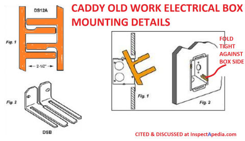
Illustration, adapted from Caddy's Old Work Box installation sheet cited below. [Click to enlarge any image]
Watch out: if you are not trained & qualified to perform electrical work you should not try it as you can cause a building fire or you may be shocked or killed. Hire a licensed electrician.
- Select the location & make the box cutout opening.
Using the new electrical box as a template, scribe and then cut an opening in the wall where the electrical box is to be installed.
- Snake the require electrical wire(s) to or through that wall opening, bringing the ends of the wires out of the wall opening and into the electrical box - normally a metal box, through an appropriate strain relief screwed to the box top or bottom.
- Connect the electrical wires to the electrical box
Tip
: having installed quite a few electrical boxes using "Madison Bars" or the Caddy(C) Old work box mount system, I note that you will pretty much always have to cut a notch at the top or bottom of the wall opening in order to re-insert the box, now with wires, back into the wall cavity, passing the metal strain relief through the opening along with the box.As long as you keep the total opening size smaller than that which can be covered by the switchplate or receptacle box cover plate, the larger opening won't be a cosmetic issue.
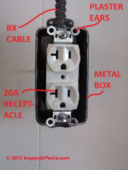
Take a look at this metal box with BX wiring shown above: you will need a bit of a notch to re-insert this box into the wall cutout in an "old work box" installation.
- Insert the electrical box into the wall cutout, tipping it to first insert the strain-relief that holds the electrical wire to the box.
Tip
: having installed quite a few electrical boxes using "Madison Bars" or the Caddy(C) Old work box mount system, I note that you will pretty much always have to cut a notch at the top or bottom of the wall opening in order to re-insert the box, now with wires, back into the wall cavity, passing the metal strain relief through the opening along with the box.As long as you keep the total opening size smaller than that which can be covered by the switchplate or receptacle box cover plate, the larger opening won't be a cosmetic issue.

- Install the mounting clips or expanding screw clip as directed by the manufacturer.
Typically, as Caddy's Old Work Box instructions show here, a flat mounting clip is inserted alongside the outside of the electrical box, maneuvered into position, the in-wall-cavity arm is pulled tight against the inner surface of the plaster or drywall, and the thin metal tab is then bent-over the edges of the metal box and folded tightly against the box sides.
Watch out: the metal tab that is folded into the electrical box must be tight against the box sides so as not to spring out and contact a live electrical terminal such as are exposed on the sides of an electrical receptacle - lest you have a dead short!
Tip:
I use my lineman's plies to pinch the old work box clip tab tightly against the sides of the electrical box.
An alternative to old work electrical box clips is to use the newer plastic swing-arm or swing-ear "old-work" electrical boxes like the round electrical "box" shown below.
Newer plastic old work boxes have an arm or "ear" that rotates outwards to secure the box by pinching against the inside of the drywall or plaster, brought tight by turning a screw.

Watch out: do not use a swing-arm electrical box mount nor any other old-work electrical box mounting system to support ceiling light fixtures or fans whose weight may exceed the box mount system rating and cause the fixture to fall from the ceiling.
See details at PLASTIC ELECTRICAL BOX REPAIR
Suppliers of Old Work Electrical Box Mounts, Clips, Supports - "Madison Bars"
- Appleton: 896, HI-102
- Arlington: SBS
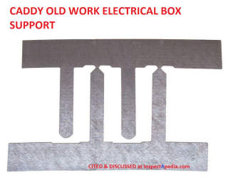
- Caddy: DSI2A - widely-distributed including https://rexel-cdn.com/
Caddy (R) OLD WORK ELECTRICAL BOX [PDF] -
- Cooper B-Line: BB33, BB33L
- Crouse-Hinds: TP708
- Dottie: SBS165
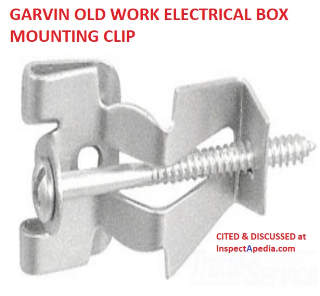
- Garvin OWC Old Work METAL BOX CLIP [PDF] Garvin Industries Tel: 1-847-455-0188 Email: info@garvinindustries.com Website: www.garvinindustries.com
https://inspectapedia.com/electric/Garvin-Old-Work-Box-Clip-Specifications.pdf - Hubbell-RACO Grip-Lok(R) OLD WORK SWITCH BOX INSTALLATION INSTRUCTIONS [PDF] model #8977, used with any deep switch box that has ears, sport 1 7/8" long legs, allows use of a conventional metal electrical box as an "old work" box for installation into an existing wall or ceiling. (Instructions courtesy of Home Depot stores).
Raco: 8977

Above: Madison Electric Products Madison 102 Switch Box Support, - Galvanized Steel Material; 5-1/4 Inch L X 2-1/4 Inch H Size; 500 Pair Standard Package; RoHS Compliant; Packaging Type Bulk
- Madison Electrical Products, 31855 Van Dyke, Warren, MI 48093 USA, Tel: (586) 825-0200 Website: https://madisonelectric.com or alternative website info: HQ: Solon, Ohio, distribution facility in Duluth, Georgia, Tel: 1-800-631-7775 Website: https://meproducts.net/ Email: contactus@meproducts.net or info@madisonelectric.com
Also see the ceiling light fixture support box described
at CEILING LIGHT FIXTURE INSTALLATION
Website excerpt: In April of 1914, Morris H. Blumberg formed the Morris Blumberg Company in an old industrial building on Woodward Ave. in Detroit. ... what today is Madison Electric Company, one of the largest electrical and electronic distribution firms in the country. The growth we have achieved over the past 100+ years is certainly attributable to Mr. Blumberg, his brother Max who joined him in 1916, and to the subsequent generations (now into our fourth) who have managed the business. ... In 1957, Madison Electric Company of Ann Arbor was founded by the Madison management team and one of their outside salesmen. - retrieved 2020/04/24 original source: https://madisonelectric.com/about-us/
- Thomas & Betts: Steel City OLD WORK ELECTRICAL BOX RETROFIT CLIPS SPECIFICATIONS [PDF] Steel City: 820D from Thomas& Betts, Tel: 901-252-8000, Tech Support: 888-862-3289, Website: www.tnb.com
This document describes both Old-Work switch box steel mounting holder #820D and Old-Work Box Support Clips (screw-secured) #OWC and OWC-Swing-Ear.
- Topaz "F" Clip
Historical Patents of Old Work Electrical Boxes & Devices
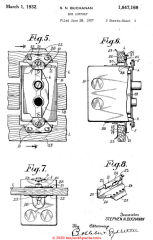 These U.S. patents describing devices for securing or mounting "old work" electrical boxes are arranged chronologically from oldest to newer inventions. In the U.K., Australia, New Zealand, Europe and other parts of Asia and Latin America other companies, inventions, and devices will, of course, have different ages and dates. Contributions to this list are invited from all readers.
Above; Buchanan's electrical box support patent from 1932.
[Click to enlarge any image]
- Wagner, Joseph F. "Junction-box." U.S. Patent 1,090,805, issued March 17, 1914.
- Thomas, Jr George C. "Cable connecter." U.S. Patent 1,644,312, issued October 4, 1927.
Excerpt:This arrangement prevents the pressure of the screw from pushing the cable G back out through the box hole, and this is an-important feature along with the fact that these improvements enable me to place the screw inside the box in this type of connecter which is an advantage because the connecter can be used for both old and new house wiring work.
- Davis, Elmer D., and Robert T. Payne. "Electrical fixture and fan support." U.S. Patent 1,824,708, issued September 22, 1931.
- Buchanan, Stephen N. BOX SUPPORT [PDF] U.S. Patent 1,847,169, issued March 1, 1932.
Excerpts:
One of the main purposes of the invention is to provide means to anchor a box on or 1n the wall or to the wall lath without employing screws, nails or other means of the usual and well known kind for securing the/ box to the A further object is to produce a one piece box support which is capable of being easily and quickly snapped or clipped onto the edge of the wall or to a lath, whereupon the box is then mounted on the support, the entire operation being carried out without the use of nails or screws which avoids splitting, breaking or damaging the wall or lath thereof.A further object is to produce a box support which is also capable of holding a switch block, plug receptacle, or other electric contact making device within the box without the use of screws.
In other words, this latter object is in addition to the first one stated so that by the use of my invention, a box, together with a switch block (or other electric contact making device, may be mounted in a wall without the use of screws or nails.
- Buchanan, Stephen N. ADJUSTABLE SUPPORTING MEANS [PDF] U.S. Patent 1,855,751, issued April 26, 1932.
Note: an early, separate, adjustable support clamp for mounting electrical boxes.
Excerpt: This invention relates to adjustable supporting means for various articles, such as conduit or outlet boxes, used in electric light wiring of buildings, conduits carrying electric light wires, signal wires,.water, gas etc. - Yanchenko, Basil J. "Grounding connecter." U.S. Patent 1,890,105, issued December 6, 1932.
- Olier, Jr Henry D. ELECTRICAL FIXTURE SUPPORTING DEVICE [PDF] U.S. Patent 1,897,954, issued February 14, 1933.
- Hubbell, Jr Harvey. UNIT WALL BOX and RECEPTCLE [PDF] U.S. Patent 1,971,302, issued August 21, 1934.
Note: this patent illustrates Hubbell's T-shaped wall plug receptacle socket openings.
Excerpt: It is, therefore, an object of the present invention to provide a receptacle structure in which the usual wall box is not necessary, and in which it is not necessary to provide a greater opening in the wall or baseboard than is required for the receptacle itself.
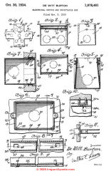
- De Witt, Burton. ELECTRICAL SWITCH and RECEPTACLE BOX [PDF] U.S. Patent 1,978,401, issued October 30, 1934.
Excerpts:A further and important object of the invention is to provide a switch or receptacle box that is automatically anchored in set position during placement thereof in a wall or other opening and eliminating the use of plaster ears so that a box may be set into an opening with less difficulty.
The electrical switch and receptacle box in this application is primarily designed for old work as distinguished from new work. The box heretofore employed comprised three wall sections including a one piece bottom and ends and separable side walls to permit gangable installation and such boxes require a series of lug and screw devices for retaining the separable walls in assembled formation.
The end walls of the known box carry mounting plates or plaster ears to facilitate the mounting of the box by means of the plaster ears on studding or other support.
The screws for attaching the plaster ears to the end walls of the box project interiorly of the box and are exposed to the wire leading from a switch and frequently produce what is known in the trade as a swinging ground.
- Seckinger, George D. OUTLET BOX HANGER [PDF] U.S. Patent 2,032,636, issued March 3, 1936.
Excerpts: By way of explanation, it may be stated that the locating of an outlet box of the kind used by electricians is a somewhat difficult task, either on new work or on old work.
The location of the box presupposes that the carpenter will provide a proper support for it. Sometimes the support is not properly located on new work, and it very often has to be provided on old work.
There are problems such as placing the box in a level and in a symmetrical position, in properly spaced relation horizontally, to the frame of a door, and the like.
The foregoing being understood, it may be stated that the object of the present invention is to provide a simple bracket whereby an outlet box may be located properly under almost all of the conditions that can be met with in actual practice, the bracket being adapted to the use of practically every outlet box now found on the market.
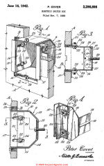
- Cover, Peter, ELECTRIC SWITCH BOX [PDF] U.S. Patent 2,286,898, issued June 16, 1942.
Excerpt:One of the principal objects of my invention is to provide a switch box equipped with inner and outer elements for securing the box within the aperture of the wall. Another object of my invention is to provide a box equipped with adjustable sides controlled by a securing means.
A further object of my invention is to provide a switch box of the above described character which is adaptable for use in connection with old as well as new work by means of the several adjustments for various widths of apertures or thicknesses of walls.
- Robert, Haynes. OUTLET COLLAR FLANGE [PDF] U.S. Patent 2,374,993, issued May 1, 1945.
Excerpt:In many places where electrical outlet boxes are required, especially in connection with old work, there is not sufficient working room for a proper installation, such as could be 'done on new work, and when the ordinary box and hanger are employed, the hanger bar rests on the upper surface o f the ceiling.
There is no way of fastening the hanger bar, unless the ceiling is cut away to give access to the, hanger: but a cutting away of the ceiling is undesirable, because it calls a plasterer on the job, to close the breach in the ceiling. The present invention aims to provide such a structure whereby the difficulties above referred to may be remedied,` novel means being employed in [making a ?] place and holding it securely anchored.
- Kolb, Walter G. "Convenience outlet." U.S. Patent 2,459,659, issued January 18, 1949.
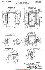
- Shepard, Frank B. WALL BOX OUTLET MOUNTING [PDF] U.S. Patent 2,586,728, issued February 19, 1952.
Note: this is an early F-clip or clip type electrical box mounting device.
Excerpts:The object of the invention is to provide a fixture which will facilitate the installation of various sized switch boxes in wall boards of buildings.
Another object of the invention is to provide a fixture for maintaining a switch box anchored in a wall board opening even though the switch box be subjected to impact and other stresses.
A further object of the invention is to provide a supporting fixture for switch boxes which is extremely simple and inexpensive to manufacture.
... From the foregoing, it will be apparent that a device has been provided which will facilitate the installation of various types of electrical switch boxes. The devices has no sharp edges and there is provided a board area of surface contact for preventing the switch box I2 from working loose from the wall board [0. By using the supporting fixture, the user can easily install switch boxes in new or old building constructions. The fixtures are made of sheet metal, such as sheet steel, copper, aluminum, or the like, in order to conform to the necessary building codes.
- Bragg, William E. MOUNTING MEANS for FLUSH RECEPTACLES [PDF] U.S. Patent 2,767,945, issued October 23, 1956.
Excerpt:This invention relates to new and useful improvements and structural refinements in means for mounting flush type receptacles in wall recesses, and the principal object of the invention is to provide extremely simple mounting means of this type whereby the installation of a receptacle in a wall may be quickly and easily effected.
- Clark, Edward B. "Armored cable clamp for a beveled corner box." U.S. Patent 2,814,509, issued November 26,
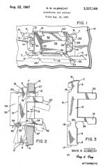
Above: the "Madison Bar" or electrical box support designed and patented by Albrecht and filed by Madison Equipment Co. granted in 1967.
[Click to enlarge any image]
- Albrecht, David B. ELECTRICAL BOX SUPPORT [PDF] U.S. Patent 3,337,168, issued August 22, 1967. Application filed by Madison Equipment Co.
Excerpts:
David B. Albrecht, Shaker Heights, Ohio, assignor to Madison Equipment Company, Cleveland, Ohio, a corporation of Ohio Filed Aug. 18, 1965, Ser. No. 480,718 5 Claims. (Cl. 24827) ABSTRACT OF THE DISCLOSURE The disclosure relates to a switch box securing device which is a fiat thin metal bar with laterally extending specially removed fingers integrally formed with one edge of the bar.The bar terminates in a flat end a distance from one finger and terminates in a beveled end at the other end. A cutaway portion in the finger remote from the beveled end extending from a point intermediate the end of one finger and terminating in the adjacent side of the bar.
A recess is formed along the opposite edge of the bar from that which the fingers are attached to accommodate the laterally protruding switch box ganging means, and a wall embedding projection emanating from the same edge of the bar as the fingers at a position intermediate one of the fingers and a terminal end of the bar.
This invention relates to electrical wiring products and more particularly to an electrical box support for securing electrical switch boxes into wall openings.
In the placement of electrical switch boxes at desired wall positions of buildings which have already been constructed or into buildings which have walls constructed out of commercially available materials such as wallboard, plaster, wood, etc., it has been found expedient to employ electrical switch box straps of a construction which include a thin flat sheet metal strip having an edge which engages the rearward surface of the wall, and which has laterally projecting fingers formed integrally with the rear wall surface engaging edge.
The fingers are made of a resilient material and are capable of being bent about the switch box side walls to prevent outward movement of the box relative to the wall aperture.
Switch boxes in the most usual form are of the well known rectangular type. When placed into the accommodating wall aperture, the inward movement of the switch box is limited by protuberances or ears, which are mounted in opposed projecting relationship to the upper and lower walls of the box, engaging the outward surface of the wall.
However, unless appropriate means are provided to limit the outward movement of the box it is obvious that the box will not be held in the appropriate wall aperture. It is the purpose of my electrical switch box support to engage the rear of the wall and provide outwardly extending fingers which are clamped to the sides of the switch box to prevent any forward movement of the box.
In addition, modern switch boxes are provided with suitable clamping means on the upper and lower surfaces which cooperate with suitable compatible clamping means carried by the side Walls thereof to permit a plurality of individual switch boxes to be ganged together where the installation so requires.
...
Continue reading at ELECTRICAL RECEPTACLE LOCATIONS or select a topic from the closely-related articles below, or see the complete ARTICLE INDEX.
Or see these
Electrical Box Articles
- ELECTRICAL BOX TYPES
- CEILING LIGHT FIXTURE INSTALLATION
- ELECTRICAL BOX SCREW REPAIR
- ELECTRICAL BOX SCREW REPAIR, METAL BOX MENDER
- EXTERIOR ELECTRICAL BOX REPAIR
- METAL ELECTRICAL BOX SCREW REPAIR
- OLD WORK ELECTRICAL BOXES for RETROFIT
- PLASTIC ELECTRICAL BOX REPAIR
- ELECTRICAL BOX GROUND WIRING
- ELECTRICAL OUTLET, HOW TO ADD & WIRE - home
- ELECTRICAL OUTLET, HOW TO ADD in OLDER HOME
- ELECTRICAL RECEPTACLE HEIGHT & CLEARANCES
- ELECTRICAL RECEPTACLE LOCATIONS
- OLD HOUSE ELECTRICAL SYSTEMS
- OLD HOUSE ELECTRICAL GROUNDING
- SIZE of WIRE REQUIRED for ELECTRICAL RECEPTACLES for receptacle circuits and similar wiring situations
Suggested citation for this web page
OLD WORK ELECTRICAL BOXES for RETROFIT at InspectApedia.com - online encyclopedia of building & environmental inspection, testing, diagnosis, repair, & problem prevention advice.
Or see this
INDEX to RELATED ARTICLES: ARTICLE INDEX to ELECTRICAL INSPECTION & TESTING
Or use the SEARCH BOX found below to Ask a Question or Search InspectApedia
...
Ask a Question or Search InspectApedia
Try the search box just below, or if you prefer, post a question or comment in the Comments box below and we will respond promptly.
Search the InspectApedia website
Note: appearance of your Comment below may be delayed: if your comment contains an image, web link, or text that looks to the software as if it might be a web link, your posting will appear after it has been approved by a moderator. Apologies for the delay.
Technical Reviewers & References
Click to Show or Hide Citations & References
Publisher InspectApedia.com - Daniel Friedman
How to Install a Old Work Electrical Box
Source: https://inspectapedia.com/electric/Old-Work-Electrical-Boxes.php
0 Response to "How to Install a Old Work Electrical Box"
Post a Comment